Split Taper Bushing Dimensions and Size Chart Explained
- Share
- Issue Time
- Feb 4,2026
Summary
Understand split taper bushing dimensions, size codes, tolerances, and shaft matching principles. Includes a practical size chart example and selection guidance.
In power transmission systems, split taper bushings are often treated as simple components. However, dimensional accuracy directly affects torque transmission, shaft alignment, vibration stability, and long-term reliability.
Understanding how to read a split taper bushing size chart is far more important when selecting or replacing a unit. If you have already reviewed our guide on What Is a Split Taper Bushing, this article goes one step further — into the actual dimensional data that determines compatibility.
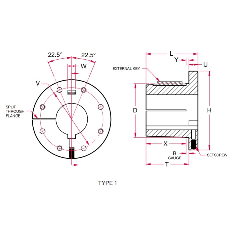
Key Dimensions of a Split Taper Bushing
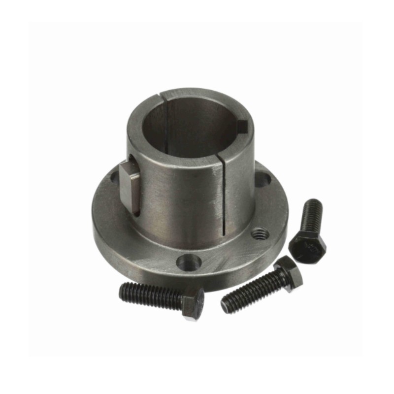
A split taper bushing is defined by several critical geometric parameters. Each one influences performance in a different way.
Outside Diameter
The outside diameter must precisely match the mating hub bore. Even minor deviations can affect seating depth and clamping force. OD tolerance ensures concentricity once installed.
Bore Diameter
The bore determines shaft compatibility. This dimension must align with the shaft diameter and keyway configuration. Standard bushings are available in both inch and metric bores, depending on market demand.
Taper Angle and Taper Length
The taper converts bolt torque into radial compression. If taper geometry does not match the hub, the bushing will not seat correctly, reducing holding strength and increasing wear.
Flange Diameter and Bolt Circle
The flange contains mounting holes used to draw the bushing into the hub. Bolt circle precision ensures uniform pressure distribution during tightening.
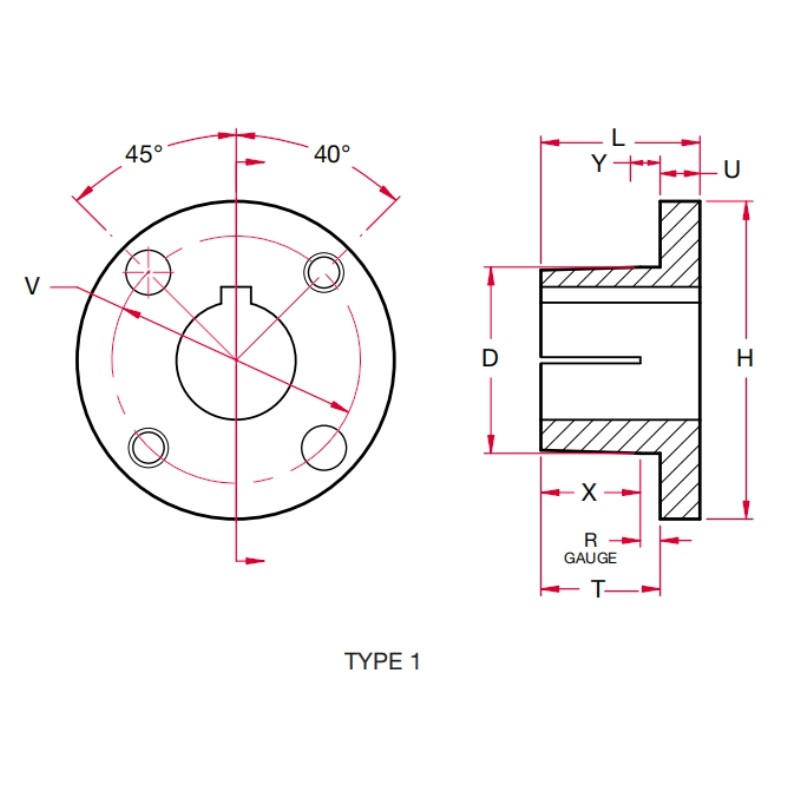
Split Taper Bushing Size Chart
G and H Split Bushing
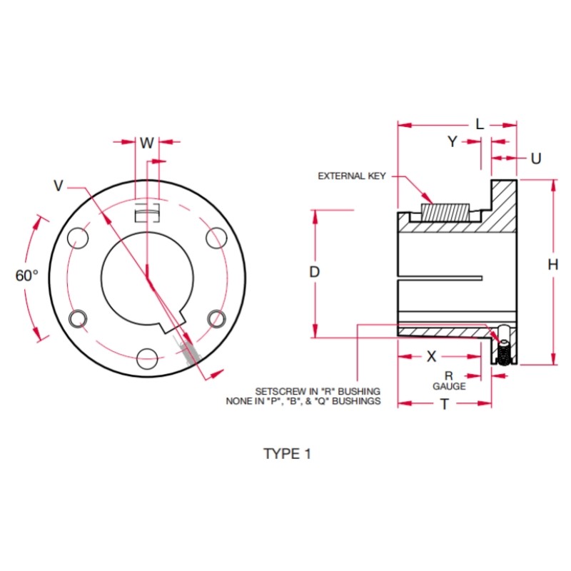
P, B, Q, and R Split Bushing
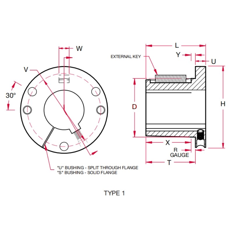
S and U Split Bushing
W and Y Split Bushing
For complete dimensions and detailed specifications, please visit our split taper bushing full-size page.
Split Taper Bushing Tolerances and Fit
Dimensions alone are not enough. Tolerances determine split taper bushings' performance. For example:
1) Bore tolerance affects shaft grip.
2) Surface finish influences friction.
3) Concentricity impacts vibration and bearing life.
Poor machining control may lead to uneven clamping or premature wear. That is why reputable manufacturers maintain strict inspection procedures, especially for taper surfaces and bore concentricity. If you are evaluating alternatives — especially for brand replacements — tolerance control is more critical than logo identity. This is exactly why our split taper bushings are engineered with controlled tolerances and verified inspection processes, providing a reliable alternative without compromising performance.
Matching the Bushing to Shaft Diameter
Proper shaft matching requires more than checking nominal diameter. It also needs to consider: Shaft tolerance class, Keyway width and depth, Expected torque load, and Rotational speed.
For instance, installing a 38 mm shaft into a nominal 38 mm bore without verifying the tolerance class may result in either excessive looseness or installation difficulty.
In high-load applications, engineers may also evaluate material grade and key strength. If you previously explored our article comparing Split Taper vs QD Bushings, you'll recall that split taper systems typically offer stronger clamping — but only when dimensions are correctly matched.
When Technical Verification Is Recommended
Certain operating conditions require additional confirmation:
• High shock loads
• Reverse rotation
• Heavy industrial drives
• Non-standard shafts
In these situations, consulting a qualified supplier ensures safe performance. If you need any help, please feel free to contact us.